OK0EU QRP BEACON - More information
QRP beacon OK0EU has been working since February 18, 2003 as a part of scientific project INFRA carried out by the Institute of Atmospheric Physics, Prague. One beacon transmitter has been set up near Prague on institute ionospheric observatory in Pruhonice, where also digital ionosonde is running. Since March 2005 subsequently four additional transmitters has been installed on 3.5 MHz band to provide multipoint measurement. Frequency of tranmitters are 3594.492 (QTH Vackov, JO60EF), 3594.496 (QTH Dlouha Louka, JO60TP), 3594.500 (QTH Panska Ves, JO70GM), 3594.504 (QTH Pruhonice, JN79GX) and 3594.508 kHz (QTH Kasperske Hory, JN69SD). On frequency 7038.500 kHz only one transmitter is working from QTH Panska Ves. The call sign is sent every minute 40 Hz up the nominal frequency by all transmitters at the same time. The call sign is then followed by a dot, which is sent in the time slot dedicated for each transmitter.
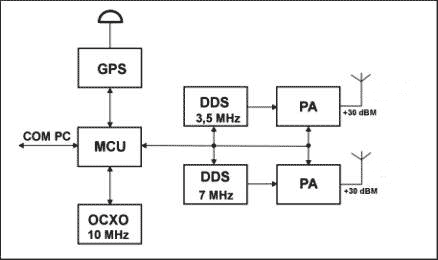
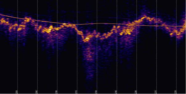
Each tranmitter works with 1W RF power to a dipole antenna. The beacon frequency is derived from the high stability OCXO 10 MHz normal. On Fig. 1 is a block diagram of the measurement system used for the ionospheric research, on Fig.2 is the beacon signal recorded by the DL4YHF SpectrumLab Sound Card software. Note the ground wave thin line curved by the receiver instability and the sky wave process from the negative to the positive Doppler shift during the sunset. The frequency changes are approx. ±0.5 Hz.
The SpectrumLab software enable you to get your own amazing pictures of fine changes of the beacon signal. It is a freeware and you can download it from DL4YHF homepage. The file with proof settings for beacon reception is available here. On Fig.3 is record of the two point measurement where time diference of ionospheric effects between two ionospheric paths is seen.
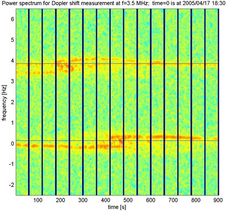
The upper line belongs to Pruhonice and the bottom one to Panska Ves transmitter.